|
||
|
||
|
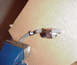
The first step to is to have a 3rd hand. Failing that, a nice little vise or bench clamp will do nicely. I like to use the RG8X mini VHF cable. It has a 95% braided shielding and, more importantly, it doesn’t take up a lot of room in the wiring conduit of either the Niagara or the Nonsuch. Slide on the reducer #UG176U and the thumbscrew coupler from a PL259 VHF connector. I like to use the VHF connectors from Amphenol. |
||
|
|
||
|
||
|
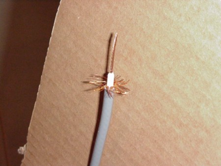
Next step is to strip the cable. Remove the cover and unravel the braiding. Trim the braiding to about 3/8 in length. Strip the center wire cover and leave about 1/4 inch of insulation above the braiding. This will ensure that the two don’t touch when you start to solder. Twist the center wire and leave long because you’ll be able to trim to length later. |
||
|
|
||
|
||
|
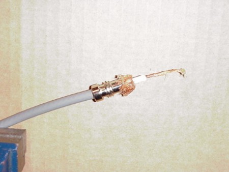
Bring up the reducer right up to the end of the outside cover and fold the braiding back. The 3/8-inch length ensures the braiding does not get caught in the threads of the reducer. Apply some soldering paste to both the core and the braiding. It also helps to tin or “presolder” the center conductor of the plug, making finishing the connector less messy. |
||
|
|
||
|
||
|
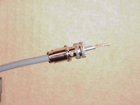
Hold the reducer firmly in place and screw on the connector and note; you should be able to see the braiding through the 4 holes between the threads and the knurled part of the plug. Now you can trim the core wire even with the end of the plug center. |
||
|
|
||
|
||
|
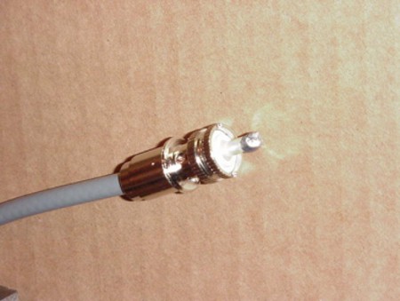
First solder the center conductor wire. Make sure the solder fills the gap with no air holes. If you end up making a ball of solder around the post don’t worry because you can file that off later. I like to use a good professional grade soldering gun with dual wattages. Weller makes a pretty good one with both 260/200-watt capacities. For solder I use a rosin core 60% tin - 40% lead in wire form for ease of handling. |
||
|
|
||
|
||
|
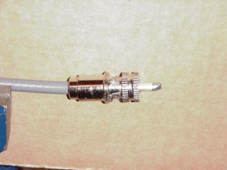
The next part is a bit tricky. Soldering the braiding to the plug. This is a “must to do” because if you do not, your radio won’t work properly. With the wire type solder you can fill each hole with a sort of sweeping motion of the soldering gun. You’ll get the hang of what I mean when you do it. It’s not necessary to put a lot of solder here, just enough to fill the hole and leave no gaps. And try to make sure you don’t get any solder on the threads. |
||
|
|
||
|
||
|
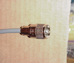
When you have filed off the ball of solder from the center conductor, slide up the knurled cover and screw it over the connector. Now you’re all finished. Call the missus and show her what you’ve done!!!! |
||
|
|
||
|
I would like to add a tip on v.h.f. antennas. Most are made to pass D.C. to ground. This is for noise reduction, so they cannot be tested with an ohmmeter for a short. To check your radio’s function, tune into a distant weather channel or ask the local Coast Guard Radio for a report. If you want a true indication, an s.w.r meter is the only reliable test. |
|
|
|
|
|

MQYR 2017